Run, Bus... RUN!
Run Bus... RUN!
Electrical
It's a bit difficult to have a single "Electrical" section, as it's something that's involved in many different parts of the bus conversion. So, this page will basically just contain some photos of wiring inside the living space of the bus that I thought might be helpful.
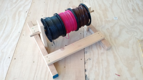
Before starting to run 12v wires for lights, etc, I found it helpful to fashion up a holder for the spools I was using (mostly 14 AWG for lights, fans, etc). Note: When you go to buy wire, just buy way more than you think you'll need, cause you're probably going to use it, and you'll get a better price on it doing so.
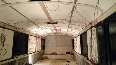
Obviously, having a plan as to where your wires need to run, before running wires, is a good thing to have as it can get kind of "hairy" sometimes. As well, be sure to use something mechanical to keep them in place. I had all these stuck up - even using Gorilla duct tape - and the next morning (because it was cold overnight) I came back to find them all on the floor. Yipee.
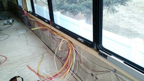
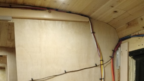
Initially wires were held in place with plastic plumber's tape and/or loose zip ties, until they could be tidied up later before wall boards were mounted.
To create some space behind the side walls for wires to run, we first mounted a 1x3 below the windows, and then screwed aluminum angle to the floor, so the plywood and OSB boards could bridge over the space. It worked well, and allowed for more room inside, width-wise.
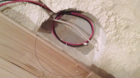
Fan wires are held in place using a piece of solid wire bridging the hole in the insulation, until a time when the ceiling hole is cut in the exterior aluminum skin.

It worked well to cross-screw some wires to hold them in place with plastic plumbers tape, until the ceiling panels were completely installed.
To avoid some sort of conduit, and keep the run as short as possible, the thicker 10 AWG wire for the front air conditioner was run between the aluminum window frames in front of the sink and up into the ceiling. This is later covered up with wood.
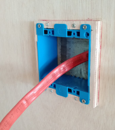
I had to build out the box for the 220v dryer outlet, as there just wasn't enough room in the wall to accommodate the depth required.

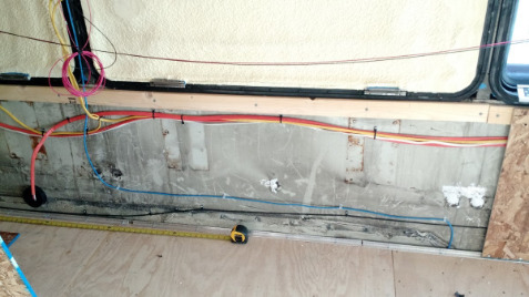
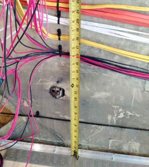
All 110v AC (14, 12 and 10 AWG) wires had to run to where the breaker panels would eventually be mounted.
As well, about half of the 12v DC wires inside needed to run to where the front fuse panel would be located.
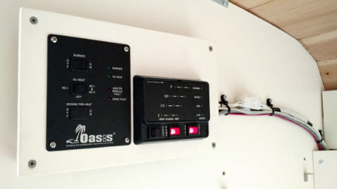
I chose this spot for the panels as it was a concealed, interior location and the closest place to the batteries and inverter (to be installed directly below, in the 1st bay) they could reasonably be put.
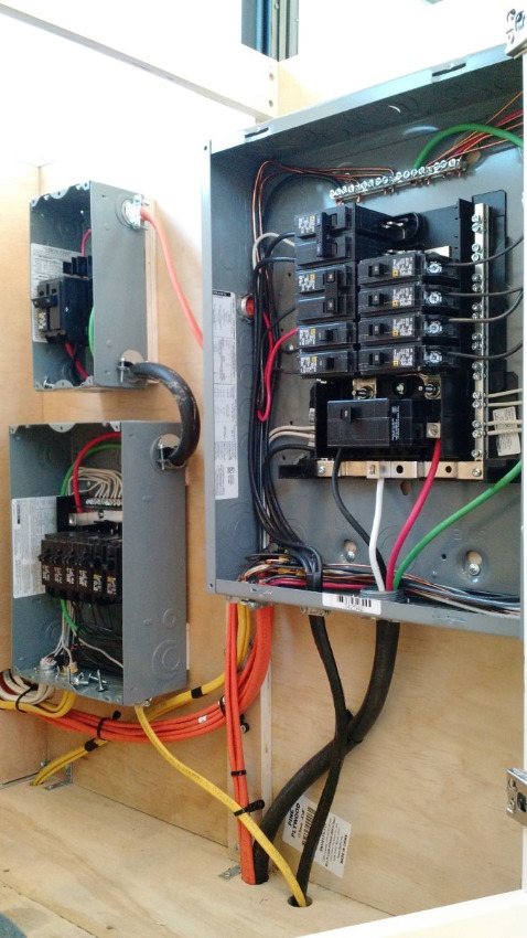
On the right is the Main panel that is fed by the transfer switch (that receives its power from either the generator, or shore power). This panel feeds the high-power devices, such as the air conditioners, and 220v washer and dryer. It also sends 30 amps down to the inverter/charger.
On the left, at the top, is simply a disconnect breaker for the Sub panel below it. Both receive their power from the inverter; either via pass-through, or inverted from the batteries. The lower-left panel feeds the outlets and any other AC-powered devices in the bus.
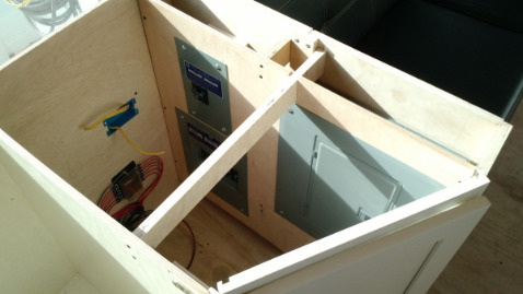
Inside the end kitchen cabinet, the AC breaker panels were installed, with the 12v DC fuse panel in the back of the
cabinet, shown finished below.
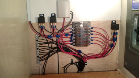
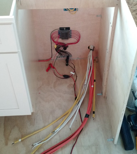
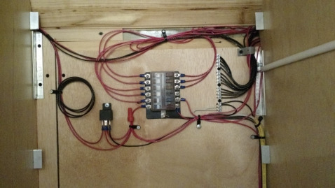
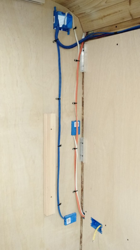
On the back wall of the closet, near the bathroom, is the rear fuse panel (shown below). About half of the 12v DC circuits are sent here. The tan box at the top of the photo is a wireless relay that controls the bay doors and the flood lights on the bus.
These connections are later covered with a board, and the space in front of it used for storage.
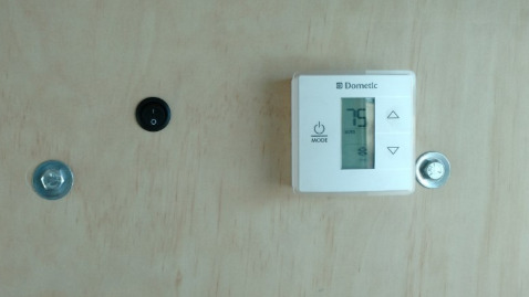
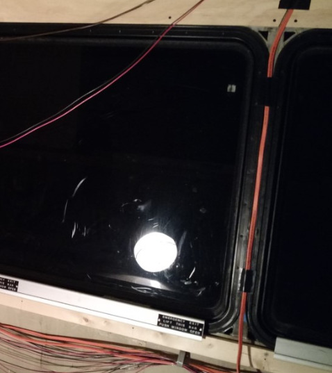
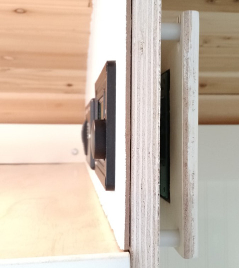
A light switch and thermostat needed to be mounted on the front side of the master bedroom wall, consisting of a single plywood board. However, it's pretty tough to hide wires inside a piece plywood.
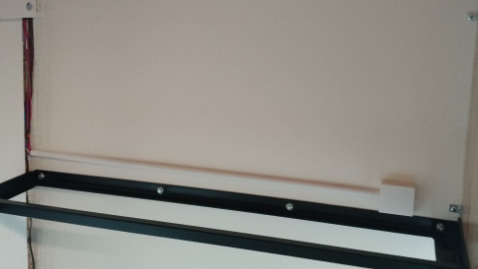
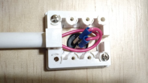
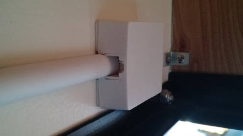
So, the wires for each were placed in a conduit on the reverse (in the top triple bunk), and I used one of those wall-mounted phone jack boxes (cheapest box-thing I could think of) was used to accommodate the extra depth needed for the round rocker switch terminals. Not super pretty, but works!

Keeping things as orderly as possible quickly became very important. Using a label maker device, I placed labels at the ends of all wires so their reason for existing didn't vanish with my short memory.
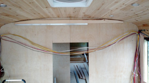
A lot of wires needed to cross from one side of the bus to the other, so they were ran above the 2x3 board used to stiffen the wall and hang the pocket door inside the first dividing wall (shown better in photos to follow).
There was just barely enough room above the 2x3 to fit all the wires between it and the ceiling boards. Since the pocket door retracted into the opposite end of this wall, I could have just cut the board shorter, but the longer board made the wall more sturdy. At this point, none of the walls were connected to the ceiling/roof, as many of them were located in between the supports/ribs in the ceiling; there wasn't anything solid above (the cedar planks) to attach them to, except the external skin of the bus (didn't really want a screw poking out!).
Later on, many of the walls became much more stable, thanks to other things (bed frames, etc) that were built around them.
But, anyway... this isn't "electrical" information! What's it doing here?!
Network cables were also run to allow access to/for wired devices we intended to take with us.
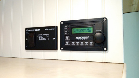
Controls for the generator and inverter/charger were mounted above the refrigerator, on the pantry wall; again one made using a single piece of plywood. So, depth was an issue, of course.
On the back side of the wall (top-left, inside the pantry), the heater remote and tank level monitor were mounted, with the necessary wires running down the back left corner of the pantry - concealed by an angled board.
The depth needed for the controls mentioned was achieved by using a separate board for mounting the inner controls, and nylon spacers to make it stand off the wall board. My better half later came and covered over the gaps with some trim to make it look more finished; more like a box.
Hint: Just a note about how valuable photos are. If you're attempting to do the same sort of thing we did, be sure to take LOTS of photos of everything. Later on, when you're covering stuff up (with wall boards, etc), you can return to photos you took and know for certain that screw you're about to put in the wall isn't going to short something out, and cause you hours of work undoing what you've already done. A picture paints a thousand words. ;-)
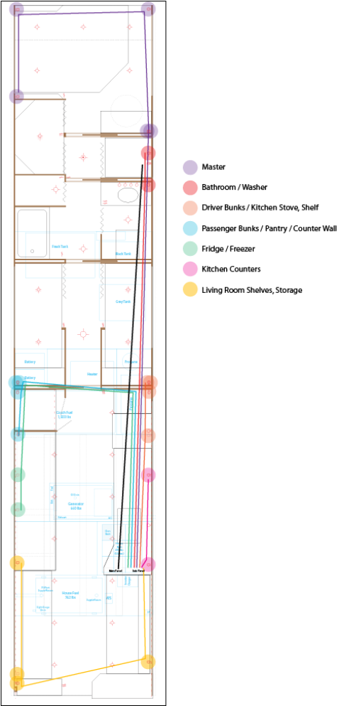
Circuits
When I was finished, a few things deviated from the electrical diagram I initially made up (left or above, depending on your screen size), but it helped to try to visualize where the AC wires needed to run, and how many outlets and devices would potentially be on each circuit.
Honestly, the whole electrical thing wasn't as difficult as it first seemed. I don't know why people get so freaked out about messing with electrical wires. Perhaps it's just fear of the unknown. I'm not a licensed electrician, but did put forth some effort to understand the basics of how electricity is properly used.
Some Basic Guidelines
1) Run wires before connecting them to a power source.
2) If the wires are connected to a power source, turn the power off before you fiddle with them. Buy a tester, and make sure it's off before you touch them (bare handed or not).
3) If the power's on, and you're impatient like me, then just make sure you don't touch more than one bare wire at the same time. (That's where they get ya... ;-).
4) Touching a 15a 110v wire won't kill you. It just feels sort of funny, and teaches you that you don't want to do that again.
5) Working with 12v is quite similar to 110v, but there's less wires to worry about, and they've got to be a lot larger (lower gauge) to move the amps you want to move.
6) The longer the wire run, the larger the wire, or more conductors (the individual little wires twisted up inside a stranded "wire") are required to move the amps you want to move. Use a smartphone app like Voltage Drop Calculator, by Southwire, to determine the size of wire you need for the distance you plan to run. Then, be liberal (the only time I'd ever suggest such ;-). With respect to functionality, you can't have too big of wire. But, using too small of wire can be dangerous, and cause things not to work. (The only downside to using wire larger than needed is you're wasting money - and copper - and it may be more difficult to work with.)
7) When in doubt call an electrician, and pick their brain. I've a few friends that heard from me often during this project. But note, they were my friend before I needed their help. Don't expect free advice from someone you've never helped before.
8) Reserved for when I think of more to add. ;-)
There are, of course, a lot of other photos that could be posted to this page, especially of other parts of the bus - the electrical runs in the bays, etc. If you find yourself wanting to see a photo of something specific that hasn't been posted, just drop us a line with your request.
© Copyright 2017-2026 Run, Bus... Run! (RBR). All rights reserved.